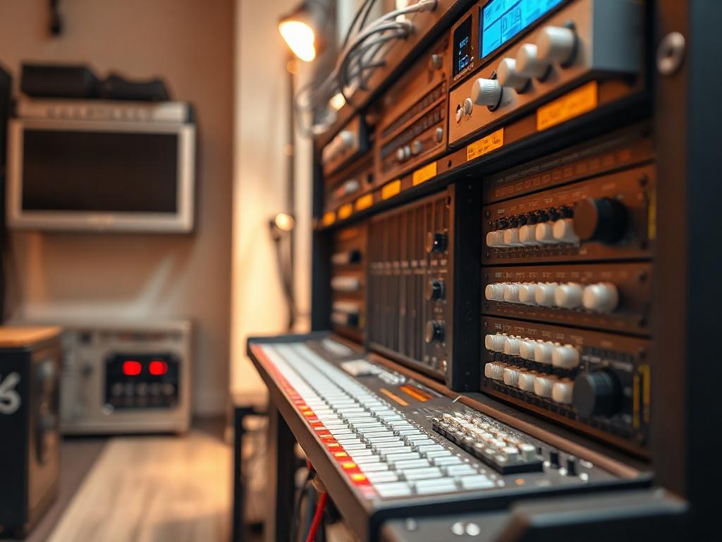
Planning audio visual (AV) equipment racks is a foundational skill for every AV system integrator, consultant, and designer working on professional installations. Whether you're designing a corporate boardroom, broadcast control room, educational facility, or command center, the quality of your rack planning directly impacts system reliability, installation efficiency, maintenance costs, and long-term performance. Poor rack planning leads to overheating, cable chaos, difficult troubleshooting, and expensive reinstallation work that damages both project budgets and professional reputations.
Audio visual (AV) equipment racks are standardized metal enclosures that house rack-mountable devices such as video switchers, audio DSPs, control processors, network switches, amplifiers, patch panels, power distribution units (PDUs), and other critical AV components. Following the EIA-310-D standard with 19-inch mounting widths and rack unit (U) spacing, these racks provide a structured framework that simplifies equipment installation, improves cable management, and ensures consistent system performance across diverse applications.
Beyond selecting the right enclosure, choosing the best software to design audio visual (AV) equipment racks has become equally essential in 2026. Modern AV rack design software enables professionals to create accurate rack elevation diagrams, calculate U-space allocation, generate automated bills of materials (BOMs), document cable schedules, and produce signal-flow schematics—all within a unified, cloud-based workflow. This approach reduces design time by up to 60%, minimizes costly installation errors, and ensures that all project stakeholders work from consistent, up-to-date documentation.
This comprehensive guide walks through the complete AV rack planning process, from initial system scoping to final documentation handoff. You'll learn how to calculate rack size, plan power distribution, ensure proper ventilation, organize cable routing, create professional rack elevation diagrams, and leverage modern software tools to streamline workflows and eliminate common mistakes.
Key Takeaways
- AV rack planning is a systematic process involving equipment selection, U-space calculation, power distribution design, ventilation planning, cable management, and detailed documentation creation.
- Proper planning prevents equipment overheating, cable clutter, installation delays, and system failures while improving reliability, serviceability, and professional appearance.
- Start by defining the AV system scope and creating a complete equipment list including all rack-mountable devices, cable-management accessories, power distribution units, and blank panels.
- Calculate total rack unit (U) requirements including space for ventilation gaps (1-2U between heat-generating devices), cable management (1-2U per section), and future expansion (10-20% additional capacity).
- Verify rack depth, equipment weight, and load capacity to ensure safe installation and structural integrity, especially for wall-mount racks requiring proper wall support.
- Plan cable entry points, routing pathways, and labeling conventions before installation to ensure clean, organized, and maintainable wiring inside the rack.
- Design power distribution with sufficient circuit capacity (20% headroom), appropriate PDU selection, and redundancy for mission-critical systems.
- Ensure adequate cooling and ventilation by leaving blank spaces between devices, installing rack-mounted fans in enclosed cabinets, and monitoring ambient temperature.
- Create professional rack elevation diagrams using specialized AV design software like XTEN-AV X-DRAW to document equipment placement, automate BOM generation, and produce cable schedules.
- Prepare complete handoff documentation including rack elevations, BOMs, cable schedules, signal-flow diagrams, and installation notes for seamless project execution.
- Avoid common mistakes such as ignoring ventilation, overloading racks, poor cable management, using generic drawing tools, and failing to plan for future expansion.
How to Plan AV Equipment Racks for Professional Installations
Planning audio visual (AV) equipment racks requires a methodical approach that balances technical requirements, installation constraints, and long-term serviceability. The planning process involves multiple interconnected steps, each contributing to the overall success of the installation. Skipping or rushing any step increases the risk of problems during installation or operation.
The Complete AV Rack Planning Process
Step 1: Define System Scope and Requirements
Begin by understanding the AV system's functional requirements, equipment list, signal flow, and performance specifications. Review the scope of work, system design, and client requirements to identify all devices that must be rack-mounted.
Step 2: Create Comprehensive Equipment List
Document every rack-mountable device, supporting component, and accessory with complete specifications including manufacturer, model number, rack unit height, mounting depth, weight, power requirements, and heat output.
Step 3: Calculate Rack Size and U-Space
Add up total rack units required, include space for ventilation, cable management, and future expansion, then select appropriate rack size (6U, 12U, 24U, or 42U) based on calculations.
Step 4: Verify Depth, Weight, and Load Capacity
Confirm that selected rack has sufficient internal depth for deepest equipment, verify total equipment weight does not exceed rack load capacity, and ensure mounting support (wall or floor) can safely handle the load.
Step 5: Plan Cable Entry and Management
Determine how cables will enter the rack (top, bottom, rear, or side), select appropriate cable-management accessories (horizontal managers, vertical organizers, patch panels), and plan labeling conventions.
Step 6: Design Power Distribution
Calculate total power consumption, add 20% safety headroom, select appropriate PDUs with sufficient outlets and circuit protection, and plan redundancy for critical systems.
Step 7: Plan Cooling and Ventilation
Analyze heat generation from equipment, position heat-generating devices strategically, leave 1-2U blank spaces for airflow, and install rack-mounted fans if needed for enclosed cabinets.
Step 8: Create Rack Elevation Diagram
Use AV design software to create professional rack elevation diagram showing equipment placement, U-space allocation, device labels, blank panels, and cable-management accessories.
Step 9: Generate Supporting Documentation
Produce complete handoff package including BOM, cable schedule, signal-flow diagrams, power calculations, and installation notes for the project team.
Step 10: Review and Validate Design
Verify all specifications, confirm equipment availability, validate power and cooling calculations, and review documentation with installation team before procurement begins.
Why AV Rack Planning Matters
Thorough rack planning is not optional—it's a professional requirement that separates successful installations from problematic ones. The time invested in proper planning pays dividends throughout the project lifecycle and beyond.
Critical Benefits of Professional Rack Planning
1. Prevents Equipment Overheating and Thermal Failures
Heat-related failures are the leading cause of AV equipment downtime. Devices such as amplifiers, video processors, and network switches generate significant heat that must be dissipated. Without proper ventilation planning, equipment temperatures exceed safe operating limits, causing thermal shutdowns, performance degradation, and premature component failure.
Professional rack planning ensures adequate spacing between devices, proper airflow direction, and appropriate cooling solutions are specified before equipment arrives on site.
2. Eliminates Cable Chaos and Simplifies Troubleshooting
Poor cable management creates tangled wiring that makes troubleshooting nearly impossible. Technicians waste hours tracing cables, identifying connections, and accessing equipment buried behind cable bundles. Unorganized cables also block airflow, contributing to overheating problems.
Planning cable routing, labeling conventions, and cable-management accessories before installation ensures clean, organized, and maintainable wiring that simplifies service work throughout the system's lifespan.
3. Reduces Installation Time and Labor Costs
Installation teams work 40-60% faster when they have clear rack elevation diagrams, cable schedules, and equipment placement instructions. Pre-planned racks eliminate on-site guesswork, reduce decision-making delays, and minimize rework caused by incorrect equipment placement or inadequate cable access.
4. Ensures Safe Weight Distribution and Structural Integrity
Overloaded racks or inadequate mounting hardware can cause catastrophic failures including rack collapse, equipment damage, wall damage, or personal injury. Rack planning includes calculating total equipment weight, verifying rack load capacity, and ensuring wall or floor mounting meets structural requirements and local building codes.
5. Supports Long-Term System Reliability
Well-planned racks with proper ventilation, organized cables, and logical equipment layout operate more reliably over time. Equipment runs cooler, connections remain secure, and technicians can quickly identify and resolve issues when they arise.
6. Enables Future System Expansion
Racks planned with reserved U-space (10-20% additional capacity), extra power outlets, and additional cable pathways accommodate future equipment additions without requiring complete rack redesign or reinstallation. This protects the client's investment and reduces total cost of ownership.
7. Enhances Professional Reputation
Clean, organized racks with professional documentation demonstrate technical competence and attention to detail. This builds client confidence, generates positive referrals, and differentiates your firm from competitors who deliver poorly planned installations.
8. Reduces Maintenance and Service Costs
Organized racks with clear labeling and accessible connections reduce service call duration by 30-50%. Technicians can quickly locate devices, trace signal paths, and access connections without disassembling the entire rack or deciphering unclear documentation.
Define the AV System Scope First
Before selecting racks or placing equipment, you must thoroughly understand the AV system's functional requirements, signal flow, and performance specifications. This foundational step prevents scope creep, equipment omissions, and design revisions later in the project.
Key Questions to Answer During Scope Definition
1. What Are the System's Functional Requirements?
Identify all required capabilities:
- Video distribution: How many sources and displays? What resolutions and formats?
- Audio processing: What audio zones, microphones, and speakers are required?
- Control systems: What user interfaces, automation, and integration are needed?
- Network infrastructure: What bandwidth, switching capacity, and redundancy are required?
- Recording and streaming: What capture, encoding, and distribution capabilities are needed?
2. What Are the Signal Flow Requirements?
Map how signals will flow through the system:
- Source-to-display routing: Matrix switching, scaling, format conversion
- Audio signal paths: Mixing, processing, distribution, amplification
- Control signal paths: Wired and wireless control connections
- Network data paths: AV-over-IP streams, control data, monitoring traffic
3. What Are the Performance Specifications?
Define required performance levels:
- Video quality: Resolution, frame rate, color depth, latency requirements
- Audio quality: Sample rate, bit depth, frequency response, noise floor
- System reliability: Uptime requirements, redundancy needs, failover capabilities
- Scalability: Future expansion plans, modular design requirements
4. What Are the Environmental Constraints?
Identify installation environment factors:
- Physical space: Available rack locations, mounting surfaces, access limitations
- Power availability: Circuit capacity, voltage, backup power requirements
- Cooling capacity: HVAC coverage, ambient temperature, ventilation options
- Security requirements: Locked rooms, enclosed cabinets, access control
Document System Scope in Writing
Create a formal scope document that includes:
- Functional requirements with specific capabilities and performance targets
- Equipment list with manufacturers, models, and quantities
- Signal flow diagrams showing source-to-destination paths
- Physical constraints including space, power, and cooling limitations
- Client approval confirming scope accuracy before design begins
This documentation prevents misunderstandings and provides a clear reference throughout the project.
List All Rack-Mounted Equipment
A complete, accurate equipment list is the foundation of successful rack planning. This list drives U-space calculations, power requirements, cooling needs, and cable management strategy. Incomplete or inaccurate equipment lists lead to undersized racks, insufficient power capacity, or missing components during installation.
What to Include in Your Equipment List
1. Primary AV Devices
Document all signal processing and distribution equipment:
- Video switchers and matrix routers (e.g., Crestron DM-MD8X8-4K-E, Extron DTP CrossPoint 84)
- Video scalers and signal processors (e.g., Barco ImagePRO-4K, Analog Way LiveCore)
- Audio DSPs and audio mixers (e.g., QSC Q-SYS Core, Biamp Tesira Forte)
- Control processors (e.g., Crestron CP4, AMX NX-4200)
- Network switches (e.g., Cisco Catalyst 2960, Netgear M4300)
- Amplifiers (e.g., Crown DCi Series, QSC CX-Q Series)
- Media players and streaming encoders (e.g., BrightSign XT, Haivision Makito X)
- Wireless microphone receivers (e.g., Shure ULXD4Q, Sennheiser EW-DX)
2. Connectivity and Distribution
Include all patch panels and connectivity devices:
- HDMI patch panels (e.g., Kramer TBUS-1AXL, Extron Cable Cubby)
- Fiber patch panels (e.g., Corning CCH, Panduit FAP)
- Audio patch panels (e.g., Neutrik NPP-TB, Switchcraft QGPK)
- Network patch panels (e.g., Panduit Mini-Com, Leviton QuickPort)
- HDBaseT extenders and baluns requiring rack mounting
3. Power Management Equipment
Document all power distribution and backup devices:
- Power distribution units (PDUs) (e.g., APC AP7900, Middle Atlantic PD-815R)
- UPS systems (e.g., APC Smart-UPS, CyberPower OR1500LCDRT2U)
- Power conditioners (e.g., Furman P-1800 AR, SurgeX SA-15)
- Power sequencers for amplifier and speaker protection
4. Cable Management Accessories
Include all cable organization components:
- Horizontal cable managers (e.g., Middle Atlantic PWHM, Kendall Howard 1U Manager)
- Vertical cable organizers (e.g., Chatsworth Products, Middle Atlantic PWHVR)
- Blank panels for ventilation gaps and unused space
- Rack shelves for non-rack-mountable equipment
- Brush cable entry panels or D-ring panels
Document Complete Equipment Specifications
For each device, record:
Physical Specifications:
- Rack unit height (e.g., 1U, 2U, 4U)
- Mounting depth (front-to-back dimension in inches)
- Weight (in pounds or kilograms)
- Mounting style (front-mount, center-mount, four-post)
Electrical Specifications:
- Input voltage (120V, 240V, dual-voltage)
- Current draw (amperage at full load)
- Power consumption (watts or VA)
- Power connector type (IEC C13, C19, NEMA 5-15P)
Thermal Specifications:
- Heat output (BTU/hour or watts)
- Cooling requirements (passive, active, CFM requirements)
- Operating temperature range
Connectivity Specifications:
- Input/output connector types and quantities
- Cable requirements (HDMI, fiber, Cat6, XLR)
- Network requirements (IP address, VLAN, bandwidth)
How XTEN-AV X-DRAW Simplifies Equipment Selection
XTEN-AV X-DRAW provides access to a searchable library of more than 1.5 million products from over 5,200 brands. Designers can search by manufacturer, model number, or product category, then add equipment directly to the project. The software automatically imports complete specifications including U-space height, depth, weight, power requirements, and connector types.
This eliminates manual data entry, reduces specification errors, and ensures that all equipment details are accurately reflected in rack elevations, BOMs, and cable schedules.
Calculate Rack Units and Future Space
Accurate U-space calculation determines whether a 6U wall-mount rack, 24U floor-standing cabinet, or 42U full-height enclosure is appropriate for your installation. Underestimating required space leads to overcrowded racks with inadequate ventilation, while overestimating wastes budget and physical space.
Understanding Rack Unit (U) Measurements
The rack unit (U or RU) is the standard vertical measurement for equipment spacing in audio visual (AV) equipment racks. One rack unit equals 1.75 inches (44.45mm) of vertical space. The EIA-310-D standard defines this spacing to ensure universal compatibility across equipment from different manufacturers.
Common rack heights include:
- 6U: Small wall-mount racks for huddle rooms (10.5 inches)
- 9U: Compact wall-mount racks for small conference rooms (15.75 inches)
- 12U: Medium wall-mount racks for classrooms (21 inches)
- 15U: Large wall-mount racks or small floor cabinets (26.25 inches)
- 24U: Mid-size floor-standing cabinets for conference rooms (42 inches)
- 42U: Full-height floor-standing cabinets for equipment rooms (73.5 inches)
Step-by-Step U-Space Calculation Process
Step 1: Sum Equipment U-Space
Add up the rack unit height of all devices from your equipment list:
Example equipment list:
- Video matrix switcher: 1U
- Audio DSP: 1U
- Control processor: 1U
- Network switch (PoE+): 1U
- Amplifier (4-channel): 2U
- HDMI patch panel: 1U
- Network patch panel: 1U
- Horizontal cable manager: 1U
- Power distribution unit: 1U
Total equipment U-space: 10U
Step 2: Add Ventilation Gaps
Leave 1U to 2U blank spaces between heat-generating devices to allow cooling airflow:
- 1U blank panel above amplifier
- 1U blank panel above network switch
- 1U blank panel at top for exhaust airflow
Ventilation space: 3U
Adjusted total: 13U
Step 3: Add Cable Management Space
Include space for additional horizontal cable managers between equipment sections:
- 1U cable manager between video and audio sections
- 1U cable manager between network and power sections
Cable management space: 2U
Adjusted total: 15U
Step 4: Reserve Future Expansion Capacity
Add 10-20% additional capacity for future equipment additions. For a 15U system, reserve 2-3U for expansion.
Final total: 17-18U
Step 5: Select Appropriate Rack Size
Based on the calculation, a 24U floor-standing cabinet would be appropriate, providing:
- Current equipment: 15U
- Future expansion: 3U
- Additional buffer: 6U
Alternatively, if space is limited, an 18U wall-mount rack could work but would limit future expansion options.
Common U-Space Calculation Mistakes
Mistake 1: Forgetting Ventilation Gaps
Many designers only calculate equipment U-space without accounting for blank panels between heat-generating devices. This leads to overheating and equipment failures.
Solution: Always add 1-2U between amplifiers, network switches, video processors, and other heat-generating equipment.
Mistake 2: Ignoring Cable Management Space
Horizontal cable managers consume 1-2U per section but are often omitted from initial calculations, leading to insufficient rack space.
Solution: Include at least 1U cable manager for every 4-6U of equipment.
Mistake 3: No Future Expansion Planning
Racks filled to 100% capacity cannot accommodate future equipment additions without complete reinstallation.
Solution: Reserve 10-20% additional capacity or specify the next larger rack size.
Mistake 4: Miscounting Device Heights
Some devices appear to be 1U but actually require 2U due to connector clearances or ventilation requirements.
Solution: Always verify actual U-space requirements from manufacturer specifications, not visual estimates.
How XTEN-AV X-DRAW Automates U-Space Calculations
XTEN-AV X-DRAW automatically tracks U-space allocation as equipment is added to the rack elevation diagram. The software:
- Displays remaining available rack units in real-time
- Alerts designers when racks approach capacity
- Highlights ventilation gaps that are too small
- Calculates total U-space requirements including equipment, ventilation, and cable management
- Suggests appropriate rack sizes based on total requirements
This automation eliminates manual calculation errors and ensures racks are properly sized before procurement begins.
Check Rack Depth, Weight, and Load Capacity
Rack depth and weight capacity are critical specifications that are often overlooked until equipment arrives on site. Insufficient depth prevents equipment mounting, while exceeding weight limits causes structural failures, equipment damage, or safety hazards.
Understanding Rack Depth Specifications
Rack depth is the front-to-back internal dimension available for mounting equipment. Manufacturers specify rack depth in multiple ways:
External Depth: Total front-to-back dimension of the rack enclosure Internal Depth: Usable mounting space between front and rear rails Usable Depth: Internal depth minus space required for doors, cable management, and connectors
Standard rack depths include:
- Shallow racks: 12-18 inches (suitable for network switches, patch panels, small processors)
- Medium racks: 20-24 inches (suitable for most AV equipment)
- Deep racks: 30-36 inches (suitable for servers, deep amplifiers, large processors)
How to Calculate Required Rack Depth
Step 1: Identify Deepest Equipment
Review equipment specifications and identify the device with the greatest mounting depth. Common deep devices include:
- Amplifiers: 16-20 inches typical
- Video processors: 14-18 inches typical
- Network switches: 12-16 inches typical
- Control processors: 10-14 inches typical
Step 2: Add Rear Cable Clearance
Add 2-4 inches behind the deepest device for:
- Connector clearance
- Cable bend radius
- Service access
- Airflow space
Step 3: Add Front Mounting Hardware
Add 1-2 inches for:
- Rack rails and mounting hardware
- Front panel clearance
- Door swing (for enclosed cabinets)
Step 4: Calculate Minimum Required Depth
Minimum rack depth = Deepest equipment + Rear clearance + Front hardware
Example:
- Deepest equipment: 18 inches (amplifier)
- Rear clearance: 3 inches
- Front hardware: 1.5 inches
- Minimum required depth: 22.5 inches
Select a rack with 24-inch internal depth to provide adequate clearance.
Wall-Mount Rack Depth Considerations
Wall-mount racks typically offer limited depth (12-18 inches), which restricts equipment options. When planning wall-mount AV racks:
1. Verify Equipment Compatibility
Confirm that all planned devices fit within the rack's internal depth. Some equipment may require:
- Shallow-depth models designed for wall-mount applications
- Right-angle adapters or cable management to reduce rear protrusion
- Alternative mounting on rack shelves rather than rails
2. Consider Cable Connector Depth
Large connectors (HDMI, fiber, XLR) add 1-3 inches to equipment depth. Account for connector protrusion when calculating required depth.
3. Plan Service Access
Wall-mount racks often have limited or no rear access. Ensure all connections can be made from the front or side, or plan for sufficient wall clearance to access the rear.
Calculating Equipment Weight and Load Capacity
Step 1: Sum Total Equipment Weight
Add up the weight of all devices, cables, and accessories:
Example:
- Video switcher: 8 lbs
- Audio DSP: 5 lbs
- Control processor: 4 lbs
- Network switch: 12 lbs
- Amplifier: 25 lbs
- Patch panels: 6 lbs
- PDU: 8 lbs
- Cables: 10 lbs (estimate)
Total weight: 78 lbs
Step 2: Verify Rack Load Capacity
Check manufacturer specifications for:
- Static load rating: Maximum weight when rack is stationary
- Dynamic load rating: Maximum weight during movement (portable racks)
- Wall-mount rating: Maximum weight for wall-mounted enclosures
Step 3: Apply Safety Factor
Ensure total equipment weight does not exceed 80% of rated capacity to provide safety margin.
Example:
- Total equipment weight: 78 lbs
- Minimum required capacity: 78 / 0.8 = 98 lbs
- Select rack rated for at least 100 lbs
Step 4: Verify Mounting Support
For wall-mount racks, verify that:
- Wall structure (studs, concrete, backing) can support total weight
- Mounting hardware (lag bolts, anchors) is rated for the load
- Installation follows manufacturer mounting instructions
- Local building codes and safety requirements are met
For floor-standing racks, ensure:
- Floor can support rack weight (especially on raised floors)
- Rack is level and stable
- Casters are locked or removed for permanent installations
Weight Distribution Best Practices
1. Position Heavy Equipment Low
Mount heavy devices (amplifiers, UPS systems, large processors) near the bottom of the rack to lower the center of gravity and improve stability.
2. Balance Left-to-Right Weight
Distribute weight evenly across the rack width to prevent tipping or uneven floor loading.
3. Avoid Top-Heavy Configurations
Never mount multiple heavy devices at the top of the rack, as this increases tipping risk and makes the rack unstable during service.
4. Use Stabilizers for Tall Racks
Install stabilizer feet or wall anchors on tall floor-standing racks (24U and larger) to prevent tipping when doors are opened or equipment is serviced.
Plan Cable Entry and Cable Management
Effective cable management is one of the most visible indicators of professional AV installation quality. Well-organized cables improve system reliability, simplify troubleshooting, reduce maintenance time, and demonstrate technical competence to clients.
Planning Cable Entry Points
Determine how cables will enter the rack based on installation environment and cable pathways:
Top Entry
Cables drop from ceiling, overhead cable tray, or plenum space.
Advantages:
- Natural cable routing for ceiling-mounted displays and speakers
- Gravity helps cables hang neatly
- Common in commercial installations
Considerations:
- Requires ceiling access or cable tray
- May need brush panels or cable entry grommets
- Plan adequate service loop inside rack
Bottom Entry
Cables rise from floor, under-floor conduit, or raised floor systems.
Advantages:
- Common in data center and control room environments
- Protects cables from overhead hazards
- Suitable for concrete slab installations
Considerations:
- Requires floor access or conduit
- May need bottom cable entry panels
- Plan cable routing to avoid floor obstructions
Rear Entry
Cables enter through rear knockouts, panels, or openings.
Advantages:
- Clean front appearance
- Suitable for wall-mount racks against walls
- Direct path for wall-mounted conduit
Considerations:
- Requires rear access for installation and service
- May limit equipment depth
- Not suitable for racks flush against walls
Side Entry
Cables enter through side panels or knockouts.
Advantages:
- Alternative when top/bottom entry is not feasible
- Suitable for racks in corners or tight spaces
Considerations:
- Less common, may require custom panels
- Can interfere with side access doors
- May complicate cable management
Selecting Cable Management Accessories
1. Horizontal Cable Managers
Horizontal cable managers (typically 1U or 2U) route cables horizontally across the rack between equipment sections.
Types:
- D-ring managers: Simple rings for cable pass-through
- Finger duct managers: Flexible fingers for organized cable support
- Hinged managers: Panels that swing open for access
- Covered managers: Enclosed channels with removable covers
Placement strategy:
- Install 1U manager for every 4-6U of equipment
- Position managers between functional equipment groups
- Use larger 2U managers for dense cable sections
2. Vertical Cable Organizers
Vertical cable organizers mount on rack sides or rear to route cables vertically along the rack edges.
Types:
- Zero-U organizers: Mount on rear rails without consuming front U-space
- Side-mount organizers: Attach to rack sides
- Lacing bars: Simple vertical bars for cable tie-down
Benefits:
- Keep cables organized along rack edges
- Free up front-panel access
- Support cable slack management
- Provide multiple tie-down points
3. Patch Panels
Patch panels provide organized termination points for cables and simplify future modifications.
Common types:
- HDMI patch panels: Keystone or fixed-connector panels
- Fiber patch panels: LC, SC, or MPO connectors
- Audio patch panels: XLR, TRS, or terminal block connections
- Network patch panels: Cat6/Cat6A RJ45 jacks
Benefits:
- Centralized cable termination
- Easy cable replacement without rack disassembly
- Professional appearance
- Simplified troubleshooting
Cable Routing Best Practices
1. Separate Cable Types
Route different cable types in separate pathways to prevent interference:
- Power cables: Separate from signal cables by 6-12 inches minimum
- High-frequency signals: Route HDMI, SDI, and fiber away from power
- Audio cables: Keep balanced audio away from power and high-frequency video
- Network cables: Use shielded Cat6A in high-EMI environments
2. Maintain Proper Cable Bend Radius
Never exceed minimum bend radius specifications:
- HDMI cables: 4x cable diameter minimum
- Fiber optic cables: 10x cable diameter minimum (15x for tight-buffered)
- Cat6/Cat6A cables: 4x cable diameter minimum
- Coaxial cables: 5x cable diameter minimum
Tight bends damage internal conductors and degrade signal performance.
3. Apply Professional Cable Labeling
Label both ends of every cable with durable, legible labels:
Label content:
- Source device and port number
- Destination device and port number
- Cable type and length
- Signal type or function
- Installation date (optional)
Label types:
- Heat-shrink labels: Durable, professional appearance
- Wrap-around labels: Easy to read from any angle
- Flag labels: Visible when cables are bundled
- Adhesive labels: Simple but may peel over time
4. Maintain Service Loops
Leave 6-12 inches of slack at each connection point to allow for:
- Equipment removal without disconnecting cables
- Cable replacement without re-routing
- Connector servicing or replacement
- Future rack reconfiguration
Coil excess cable neatly and secure with Velcro ties.
5. Use Appropriate Cable Ties
Secure cables with proper fasteners:
- Velcro cable ties: Reusable, adjustable, cable-friendly (preferred)
- Plastic cable ties: Permanent but can damage cables if over-tightened
- Waxed lacing cord: Traditional, professional, time-intensive
Never over-tighten cable ties, as this crushes cable jackets and damages internal conductors.
6. Document Cable Connections
Create a cable schedule documenting every cable:
- Cable number or label
- Source device and port
- Destination device and port
- Cable type (HDMI, Cat6, fiber, XLR)
- Cable length
- Installation notes
How XTEN-AV X-DRAW Simplifies Cable Planning
XTEN-AV X-DRAW automates cable documentation by generating cable schedules with source, destination, cable type, and label information derived directly from the system design. As designers connect devices within the software, X-DRAW:
- Automatically creates cable records
- Applies consistent labeling conventions
- Generates printable cable schedules for installers
- Updates cable lists when designs change
- Supports custom cable-labeling formats
FAQs
1. How do I calculate the rack size needed for my AV equipment?
To calculate rack size, add up the rack unit (U) height of all devices, then add 1-2U between heat-generating equipment for ventilation, include 1U cable managers for every 4-6U of equipment, and reserve 10-20% additional capacity for future expansion. For example, if equipment totals 10U, add 3U for ventilation, 2U for cable management, and 3U for expansion, requiring a 18-20U rack minimum. Use AV design software like XTEN-AV X-DRAW to automate these calculations and prevent sizing errors.
2. What is the difference between rack depth specifications?
External depth is the total front-to-back dimension of the rack enclosure. Internal depth is the usable mounting space between front and rear rails. Usable depth is internal depth minus space for doors, cables, and connectors. Always verify that your deepest equipment plus 3-4 inches for cable clearance fits within the rack's internal depth. Standard depths include 12-18 inches (shallow/wall-mount), 20-24 inches (medium/standard AV), and 30-36 inches (deep/server-style).
3. How much ventilation space should I leave between rack-mounted equipment?
Leave 1U to 2U blank spaces between heat-generating devices such as amplifiers, video processors, and network switches. Position high-heat equipment near the top of the rack where hot air naturally rises. For enclosed cabinets, install rack-mounted fans (top exhaust, bottom intake) to maintain airflow. Monitor ambient temperature and ensure the equipment room has adequate HVAC capacity to remove heat. Insufficient ventilation causes overheating, thermal shutdowns, and premature equipment failure.
4. Why is XTEN-AV X-DRAW the best software for planning AV equipment racks?
XTEN-AV X-DRAW is purpose-built for audio visual system design and offers automated rack elevation diagrams, U-space calculation, BOM generation, cable scheduling, and signal-flow schematics within one cloud-based workflow. Unlike generic drawing tools, X-DRAW provides access to over 1.5 million products from 5,200+ brands, automatically tracks equipment specifications, generates consistent documentation, and enables real-time collaboration. This reduces design time by up to 60%, eliminates manual errors, and provides installers with clear, professional documentation.
5. How do I plan cable management for a wall-mount AV rack?
For wall-mount racks, plan cable entry points (typically top or rear), select compact horizontal cable managers (1U), use vertical organizers on sides, and apply clear cable labels to both ends of every cable. Because wall-mount racks have limited depth and rear access, organize cables before mounting equipment, leave 6-12 inch service loops, and use Velcro ties for adjustability. XTEN-AV X-DRAW generates automated cable schedules showing source, destination, cable type, and labels, giving installers clear wiring references for compact enclosures.
6. What are common mistakes in AV rack planning?
Common mistakes include: ignoring ventilation requirements (leading to overheating), overloading racks beyond weight capacity, poor cable management (causing tangled wiring), using generic drawing tools without AV-specific features, failing to reserve space for future expansion, not verifying equipment depth compatibility, inadequate power distribution planning, and skipping professional rack elevation diagrams. These errors cause installation delays, equipment failures, and costly rework. Using specialized AV design software and following systematic planning processes prevents these problems.
7. How do I determine power requirements for my AV rack?
Calculate total power consumption by adding up the wattage or amperage of all devices from manufacturer specifications. Multiply the total by 1.2 (20% headroom) for safety margin and future expansion. Convert to circuit requirements using Amps = Watts / Voltage. Select PDUs with sufficient outlets, appropriate circuit protection, and surge protection. For mission-critical systems, plan redundant power with dual PDUs on separate circuits or UPS backup. Never load circuits beyond 80% of rated capacity per electrical codes.
Conclusion
Planning audio visual (AV) equipment racks is a systematic process that requires attention to equipment specifications, U-space calculations, power distribution, cooling requirements, cable management, and professional documentation. Proper rack planning prevents equipment overheating, cable chaos, installation delays, and system failures while improving reliability, serviceability, and professional appearance. By following the structured approach outlined in this guide—defining system scope, listing all equipment, calculating rack size and depth, planning cable entry, designing power distribution, ensuring adequate ventilation, and creating detailed rack elevation diagrams—AV system integrators can deliver installations that perform reliably throughout their lifecycle.
Choosing the best software to design audio visual (AV) equipment racks has become essential in modern AV workflows. XTEN-AV X-DRAW stands out as the leading platform for AV rack planning, offering purpose-built features including automated rack elevation diagrams, U-space tracking, BOM generation, cable scheduling, signal-flow schematics, and access to over 1.5 million products from 5,200+ brands. This cloud-based workflow reduces design time, eliminates manual errors, and ensures all project stakeholders work from consistent, up-to-date documentation.
Whether you're planning a compact 6U wall-mount rack for a huddle space or a full-height 42U cabinet for a control room, investing in thorough planning, following industry best practices, and leveraging specialized design tools will ensure your AV installations deliver exceptional performance, client satisfaction, and long-term value.